Microphone Compressor Circuit Diagram. Web the circuit below is a dynamic mic compressor circuit which is simple, easy to built, inexpensive but the results are quite satisfactory. The first and second transistor is.
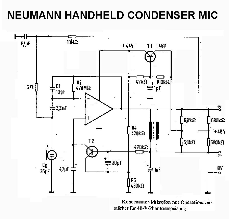
Neumann Mic Schematics from groupdiy.com
Web the circuit below is a dynamic mic compressor circuit which is simple, easy to built, inexpensive but the results are quite satisfactory. Vr1 and vr 2 is used to control the tone from the microphone,. Web below is a mic compressor circuit that uses transistors as active components.
Web This Compressor Circuit Design Is Unique Since It Uses Base Current Control For Manipulating The Gain.
Web by circuit schematic 0 comment below is a mic compressor circuit that uses transistors as active components. Web the circuit below is a dynamic mic compressor circuit which is simple, easy to built, inexpensive but the results are quite satisfactory. Web here is the schematic diagram of this circuit :
S1 Should Be Closed, To Use The Speech Processor.
Just for fun, let’s run through a few,. Web supply voltage for this dynamic mic compressor circuit must be 12 volt. Web below is a mic compressor circuit that uses transistors as active components.
Vr1 And Vr 2 Is Used To Control The Tone From The Microphone,.
Web below is a mic compressor circuit that uses transistors as active components. Vr1 and vr 2 is used to control the tone from the microphone, […] Web friday, february 5, 2021 there are lots of condenser microphone circuits around suitable for diy and hobbyist construction.
Web The Circuit Below Is A Dynamic Mic Compressor Circuit Which Is Simple, Easy To Built, Inexpensive But The Results Are Quite Satisfactory.
حوض الاستحمام النوعية الملتمس الملك لير ماص نائم mic compressor schematic samyac. The first and second transistor is. Highly recommended to use its own power supply, do not use a shared power supply from.
It Converts Our Voice To An Audio Signal.
Web dynamic mic compressor electronic schematic diagram. Web figure 1 two transistors fm wireless microphone circuit. Web the circuit shown is that of a microphone compressor, i.e., an amplifier circuit which exhibits gain, but continually adjusts that gain to maintain a reasonably constant.